Pins of microcontroller can be used as inputs or as outputs.
Output on a microcontroller (Arduino):
- We use pin of a microcontroller as output , when we want to give command - information to an external peripheral.
- The output can be either analog or digital. Are particularly the pins of microcontrollers that can be used as digital outputs or analog outputs or can combine both possibilities at the same pin, all these possibilities mentioned in datasheet of each microcontroller.
- Digital output is characterized when the mandate of the peripheral is binary 0 or binary 1. The command is transferred from the microcontroller to the peripheral with voltage (when it is powered with 5 volts), ie binary 0 is transferred to 0 volt and binary 1 are transferred 5 volts.
- For "analog output" (output which produce pulse), ie to vary the output voltage from 0 to 5 volts (100% duty cycle) if the microcontroller is powered with 5 volts. Microcontrollers have outputs (pins) which are capable of producing pulses of variable width (pwm - pulse width modulation). Parameter these pulses is their duty cycle, which determines how much time during a period is active pulse. In this way it is achieved the change of the output voltage of the pin. Ie 0 volts (0% duty cycle) to 5 volts (100% duty cycle).
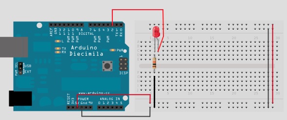
- If we want to connect an led to the pin of the microcontroller using resistor connected in series with the led, the value of which is selected according to the characteristics of the led. The reason we put resistors in wiring is to limit the current to the desired working limits of the led and the microcontroller as each pin of the microcontroller "is able" to provide a specific current at the output (eg. 20mA) if the load ( in this case we connected the led) exceeds this maximum limit (20mA) output of the microcontroller as the led will be destroyed. Each electronic component is permissible operating limits
- If we want to turn on the led at full brightness with command from microcontroller (arduino) and is not required brightness variation then connect a standard digital output.
- If we want to varied the brightness of the led, then connect to pwm output. So when we varied the duty cycle of the pulse will vary and the brightness of the led.

- In the case of leds the maximum power output of the microcontroller is sufficient for its requirements. That is, if the led to light at full brightness consumes 20 mA then output of the microcontroller will not risk to be destroyed. But if the load "pull" more current (more than 20 mA) then you risk destroying output.
- So when a load consumes more current than the allowable output of the microcontroller, then do output enhance.
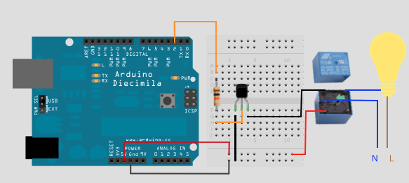
- Enhancing the output can be done by placing transistors (not the only way). The transistor is a device semiconductor which according to the value of the input voltage (microcontroller) vary the value of the output voltage (the relay coil).
- If we want to connect loads such as a lamp, a motor, etc. Operating on AC voltage at 230 Volts and we want to be activated or deactivated by the output of the microcontroller it is necessary some parts. But the relay to move the contact and activate the load must trigger the coil. To trigger coil, required e.g. 50 mA. This value is not able to provide the output of the microcontroller. So connect transistor to microcontroller output and transistor drives the relay coil. Accordingly we can control any load. We place resistor to limit the current of microcontroller output (ie, for the same reason that the place and the leds). We place diode to prevent microcontroller from current spikes.

